Mounting is perhaps the most challenging and frustrating aspect of stereo photography for beginners. The film chips have to be delicately manipulated to within fractions of a millimetre while being careful not to dirty the slide with dust or fingerprints. Incorrectly mounted slides can cause uncomfortable eye-strain which ruins the enjoyment in viewing. Nevertheless, with practice you will become adept at mounting and may come to find this part of stereo photography rewarding and creative. My goal in this article is to offer beginners some practical advice for stereo slide mounting, and discuss the choices that can be made during mounting to help you fulfill your creative vision.
Generally it is desirable that the final mounted slide is viewed from the “base” side (i.e. the non-emulsion side). If you view the slide from the emulsion side, the image will be horizontally mirrored. Just as is the case when you view a reflection in a mirror, this means that any text in the photo will be unreadable.
When you can read the printing on the film rebate, that means that the non-emulsion surface of the film is facing toward you. The orientation of the scene should appear as it did when you took the photograph. In cameras like the Sputnik, where the film takeup spool is on the left hand side of the camera, the writing will appear upside down when the image is right side up. Conversely, for film shot in cameras with the takeup spool on the right hand side of the camera, the rebate writing is upright with respect to the orientation of the image. Regardless of the camera, when viewing the “base” side of film, the rebate text will always be readable, while the rebate text will be flipped (mirrored) when viewing the emulsion side of the film. If your film contains no rebate markings, you use the fact that the “base” side is shinier than the emulsion side. If the film is curled or cupped, it is likely that the concave surface is the emulsion side.
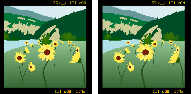
You can “preview” the image in 3D by placing the two film chips (as of yet uncut) on a lightbox and viewing using the cross-eyed method.
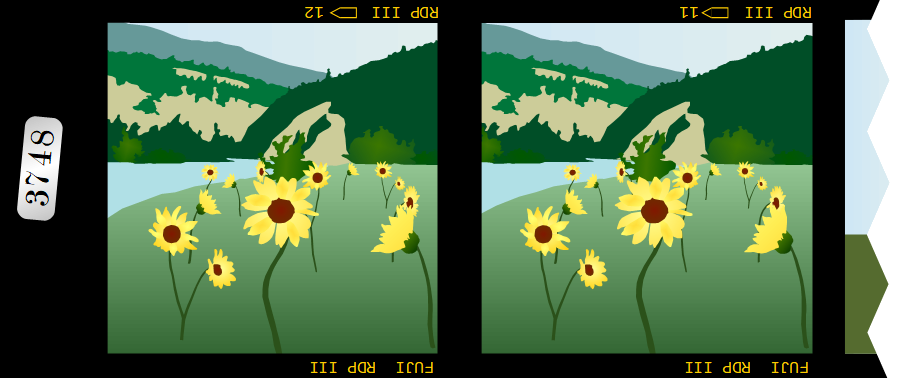
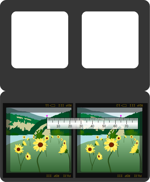
If there’s nothing obviously wrong with the slide and you are ready to mount the slide, cut the two film chips apart and swap them. With the stereo pair separated and transposed, the left hand image (here, frame 11) corresponds to the image the left eye should see, and the right image (here, frame 12) corresponds to the image the right eye should see. This means you can “parallel-freeview” the image, or use a mounting jig to view the image.
A brief word about the design of the stereo mounts

The front apertures of the standard square mounts are 50 mm by 50 mm and have slightly rounded corners. The rear apertures are slightly larger (52mm x 52mm) and have square corners. The rear apertures are slightly larger than the front apertures so that if there is a slight error when folding the mount in half, the stereo window is not “cropped” by the misalignment between the front and rear apertures. With this design, the stereo window is always set by the front apertures. The apertures on these mounts are spaced 62 mm apart. This sets the stereo window at a reasonable distance in front of the far point limit of most common medium format viewers, which likely contain lenses separated by a distance of about 65 mm. This gives exactly 3 mm (65 mm – 62 mm) of On-Film Deviation that can lie between the stereo window and the far point limit (determined by the inter-ocular distance of the handheld viewer lenses).
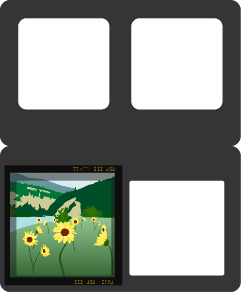
Affixing the first chip
First, crease the mount by folding it and re-opening it. Place the mount in front of you such that the larger 52 mm x 52 mm rear apertures are nearest to you, as in the image above. Tape one of the chips in the bottom aperture of its respective side (left or right) of the mount. The emulsion side should be facing down. I recommend using small tabs of tape, since you will likely need to reposition the film chip a little bit later. Most “6 x 6” medium format cameras expose an area of film approximately 56 mm x 56 mm. The front apertures (which define the stereo window) are 50 mm x 50 mm, so you have a bit of choice as to where the image should be cropped. Obviously, if there are light leaks or offending objects that are closer than the 1/30 rule (stray grass blades or twigs are common in nature photos if you aren’t careful), these should be cropped out. Otherwise, the choice should be made based on composition. Also be aware that the sharpest area of an image is in the centre, and triplet lenses like the Sputnik’s definitely fall off in sharpness towards the corners.
It’s important that the film chips are displaced along the same axis the two different images were taken. When shooting with a single stereo camera like the Sputnik, the easiest way to do this is to make sure that the bottom edge of the film is parallel with the bottom edge of the mount.
What kind of tape
There are several adhesive tapes that could be considered for mounting slides. Personally, I use standard Scotch Magic Mending tape (the green plaid label). It is not too expensive, and this tape complies with ISO standard 18916, so it is safe to use in contact with your slides. You will need to cut it into thin strips, which can take a bit more time. Some people use Wess tabs to secure the film chips in place while mounting and adjusting the position of the chips, and then use silver polyester tape (such as 3M #850) to firmly secure everything in place. You should certainly stay away from masking tapes which leave gummy residues, dry out and lose adhesion, and are not photo-safe.
Mounting choices
Now we come to the part of mounting that offers some choice. There are two different mounting philosophies:
(A) Mounting “to the window”
(B) Mounting “to infinity”
Mounting to the window
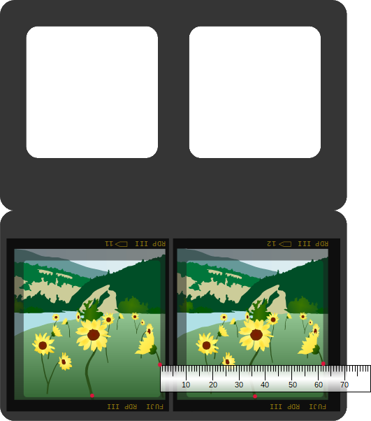
If you choose to mount to the window, you need to identify the nearest object in your scene that crosses the edge of the frame. In the image below, there are two flowers that exist in the same plane of depth (that is to say they are the same distance from the camera). The flowers cross the edge the frame at two places that are marked with red dots. When mounting to the window, equivalent points on the two film chips that correspond to the same point in 3D space (called homologs) should be separated by the same separation as the window. In the case of the medium format mounts available on this website, that is 62 mm. Usually, one point will be nearer to the camera, and that point should be set to 62 mm. If there are two points that are both equally near to the camera, and nearer than any other point, either point can be set to 62 mm, and in-so-doing “automatically”, the other point will also be set to 62 mm. This is what it means for two points to be equidistant from the camera.
Mounting to infinity
Alternatively, if you are mounting to infinity, any easily identifiable point at infinity can be chosen. The other film chip should be positioned such that the homologs (corresponding points) are separated by the lens separation of the handheld viewer. In the case of the 3D-World steal-the-light viewers, the lenses are 65 mm apart. Thus, the magenta points in the image below should be separated by 65 mm.
Choosing a mounting method
Why would you want to choose one mounting method over another? Some people prefer mounting to infinity since it makes for a consistent viewing experience when switching between slides that are all mounted to infinity. Mounting to infinity is required to present an orthostereoscopic view, that is to say where the angle formed between the line of sight from each eye to an object at a particular distance (sometimes called the “toe-in” of the eyes), is the same angle your eyes converge at when looking at an object at this same distance in the real world.
Other artists prefer mounting to the window because it brings the scene closer to the viewer. Mounting to the window can be simpler in practice, since you don’t need a ruler. For many photos, the nearest point in the image is the ground right at the bottom of the frame. If you find some easily identifiable feature near the bottom corner, like a pebble or clump of grass, simply place this feature along the left or right edge of the aperture for each film chip. Since the apertures are separated by 62 mm, you will have automatically set the near homologs to 62 mm.
Note that mounting to the window and mounting to infinity are the two boundary conditions. If you are capturing 100% of “maximum acceptable on film deviation”, there is no difference between mounting to the window and mounting to infinity!
If the far homologs are separated by more than 65 mm, the viewer’s eyes will be forced to diverge in order to fuse the image. This is strenuous on the eyes and for most people it is uncomfortable or even painful. The far homologs should never be separated by more than the separation between the lenses of the viewer.
Furthermore, if near homologs along any of the edges defined by the window are closer than 62 mm, you will perceive what is commonly called a “window violation”. This is when an object appears as if it should be in front of the window, but the window is occluding the object. This is never encountered in normal life, so your brain doesn’t really know what to make of the situation, and the view just looks “off”. When viewing images from far away (such as a viewer with longer focal length lenses), or small images on the web, the window features very prominently and violations are apparent and off-putting. It’s much more difficult to asses window violations when the image occupies a larger field of view, such as in a wide angle viewer. This also means that small window violations are less problematic in an immersive viewer, but they should none-the-less be avoided by judicious mounting.
Finishing up
After mounting the film chips, you should insert the open mount into your viewer to assess how well you’ve mounted the image. You may find various problems such as rotational errors, vertical alignment errors, or improper window placement. No worry, simply unstick the tabs of tape and adjust the film chip(s) appropriately to correct the issues.
Once you are satisfied with the mounting, firmly secure the film in place with some longer strips of tape along the edges of the film. Personally, I also like to fold some tape back on itself widthwise, making a thin tube of tape with the adhesive on the outside. I place one tube along the septum between the images, and smaller tubes above each image, below the crease.
What about that image that just doesn’t mount properly? I can’t emphasize enough that a successfully mounted image depends mostly on what was captured in camera. If there’s excessive deviation in the image, no mounting technique will make the image fusable. This shouldn’t be too much of a problem for fixed stereo base cameras like the Sputnik, unless you covered one lens and did a “cha-cha”. The only thing that can help a slide with too much depth is to crop out the offending bits of the image. Reduced height mounts, such as the landscape and panoramic mounts can be particularly useful for this. Mounting simply allows us to drag the entire scene along the z-axis and place it closer to the viewer (as in mounting to the window), or more realistically (as in mounting to infinity). The amount of depth in the stereoview (called On-Film Deviation, or OFD) is determined in the camera.
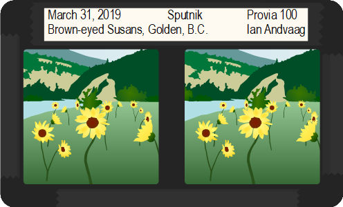
Now you can fold over the mount and close it shut. I use three pieces of tape to seal the side and bottom edges. Although not strictly required, it’s a nice touch to label your slide. If you decide to join a MF3D folio, you will need to label your slides. This is one disadvantage of these black mounts — you can’t write directly on the mounts with normal pens or markers since the ink will not be visible. Some people use pens with silver or white ink. Others type out their labels and print them onto adhesive label paper. I’m a bit paranoid and I don’t want to risk damaging my slides with materials that may interact with the dyes in the emulsion, so I cut strips of white, acid-free paper to use as labels. I just use Scotch tape to attach the paper to the top of the mount. Information you may wish to record could include: date, camera, film stock, exposure settings, title, location and your name.
Finally, you may wish to protect the slide, since camera-original slides are essentially irreproducible. Unfortunately I don’t currently stock any plastic protective sleeves, but if you head over to the MF3D Yahoo group and ask nicely, there’s a good chance someone may have some sleeves to spare.
Disclaimer: In this article, I defined maximum on film deviation (MAOFD) as the difference between the viewer inter-ocular (~65 mm) and the mount aperture spacing (62 mm). This is not exactly the same as the “viewer focal length divided by 30” rule defined by John Bercovitz. I used a different definition just to simplify the explanation.