The stereo window is an important concept for newcomers to stereo photography, but even among seasoned stereo shooters, misconceptions abound. In this article, I will attempt to carefully examine the physical origin of the window, explain why window violations ought to be avoided and discuss the concept of the in camera stereo window, which may be of use to anyone wanting to design a stereo camera. I have created an online calculator and visualization tool to accompany this article which may be helpful in understanding the mathematical relationships between the stereo base, the maximum acceptable on-film deviation, and the width of the window-violation free stereo image.
Homologous Points: How a Stereo Pair Records Depth
To fully appreciate the stereo window, we must first turn our attention to the means by which our eyes can ascertain depth in a stereo image, that is, homologous points. These are a pair of points, one in each image, which correspond to a single physical point in space in the original scene. Going forward, I’m going to call these homologs for brevity.
Imagine that you decide to draw your own stereo pair. It is a very simple drawing — just a single green dot. It is a stereo pair, so you need to draw two dots, one for the left eye, and one for the right. You have a large sheet of paper, so there is no “mount”, “frame”, or “stereo window” to worry about, it’s just a green dot floating in space against the featureless white backdrop of the paper. Let’s say for simplicity that you have an interpupillary distance of 65 mm and you want to view the image using a viewer which has lenses that are also spaced 65 mm apart. If you draw the two dots of the stereo pair such that they are spaced 65 mm apart, the point in 3D space when viewed through your viewer will appear at infinity, because your eyes will point straight ahead without converging:
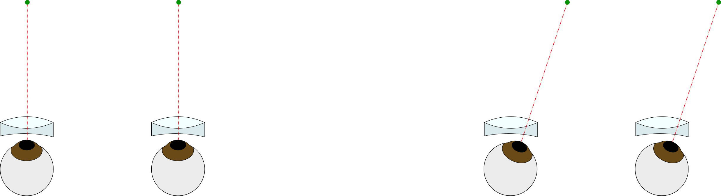
The pair of eyeballs on the left shows the case where the point is positioned on-axis with the lenses, and the right pair shows the dot positioned off to the side. In both cases, the eyes are parallel, and so the viewer sees the image of the dot as appearing at infinity.
Now, take a new sheet of paper and draw a new pair of green dots separated by a distance somewhat less than 65 mm. When viewed through the viewer, the point in 3D space will appear closer, because your eyes will have to converge to “fuse” the image:
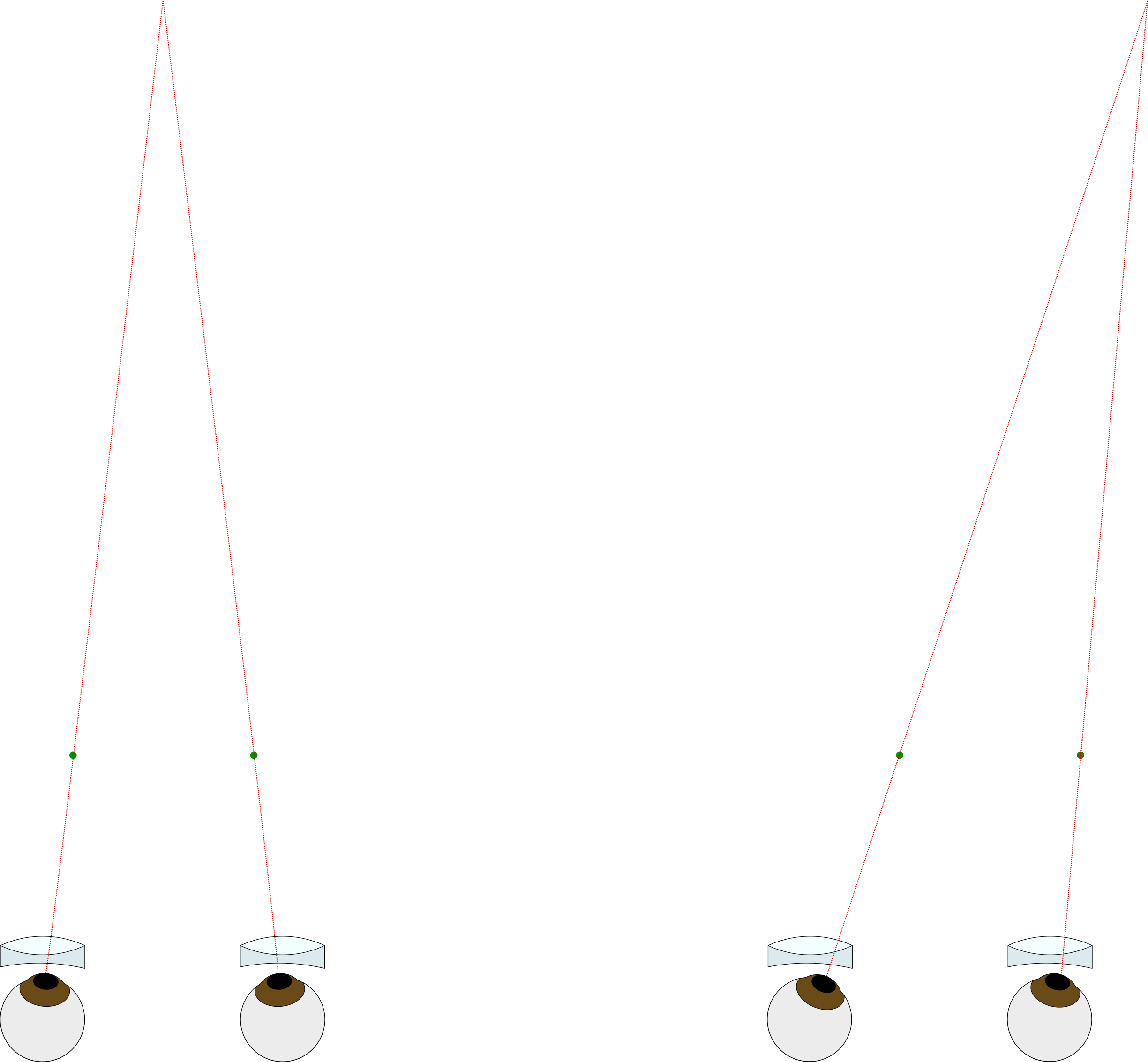
The point at which the lines converge is the “virtual location” of the image. In this example, they are only 49 mm apart, so the object would appear at ~30 cm (assuming a 75 mm viewer FL and a 65 mm interocular separation). There are many practical factors which make this much convergence unrealistic, but I needed the rays to converge at a reasonable distance to fit on this webpage! As an aside, people may talk about the “deviation” of a particular homologous pair. To calculate the deviation, you take the distance between the homologs of an object at infinity and subtract that from the homologs in questions, in this example 65 mm – 49 mm = 16 mm. Typically, for medium format, practical factors limit you to a maximum deviation about 3 mm. This 3 mm is nothing magical, and I intend to discuss how you might derive a value that is suitable for your needs in another post; for now I ask that you accept that this is somewhat reasonable so we can proceed with our investigation of the stereo window. See the footnote* at the bottom of this page for a preliminary explanation.
You can also think about what would happen if you draw the green dots at a distance greater than 65 mm — your eyes would have to diverge — this doesn’t happen in normal life and can cause eye strain and be quite unpleasant to view. So the farthest homologs in an image should be separated by no more than 65 mm, otherwise your eyes will splay out, like this:
Why do film chips need to be transposed?
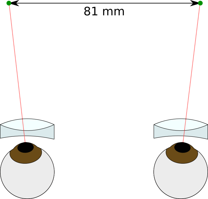
Let’s finally move from a drawing to a photograph. It is widely known that slides shot with a stereo camera onto a single roll of film must be cut apart and swapped before they may be viewed in a Brewster-style stereo viewer, but why is this the case? The above observations from the green dot thought experiment have equipped us to answer this question. Consider a camera with lenses that are separated by 65 mm. The homologs which are recorded for very distant objects will be recorded on the film 65 mm apart. The homologs for nearer objects will be recorded on the film at a distance greater than 65 mm, as in this figure:
Now, as we established in the green dot drawing example, in order to view the images “parallel” (i.e. the left eye views the left film chip and the right eye views the right film chip, such as in a Brewster viewer), the near homologs have to be closer together than 65 mm, such that our eyes converge. This is why the film chips must be transposed. So we cut the film apart, and position them such that the far homologs are 65 mm apart once again, but with the Left/Right images swapped. Now the near homologs will be spaced closer together than the far homologs.
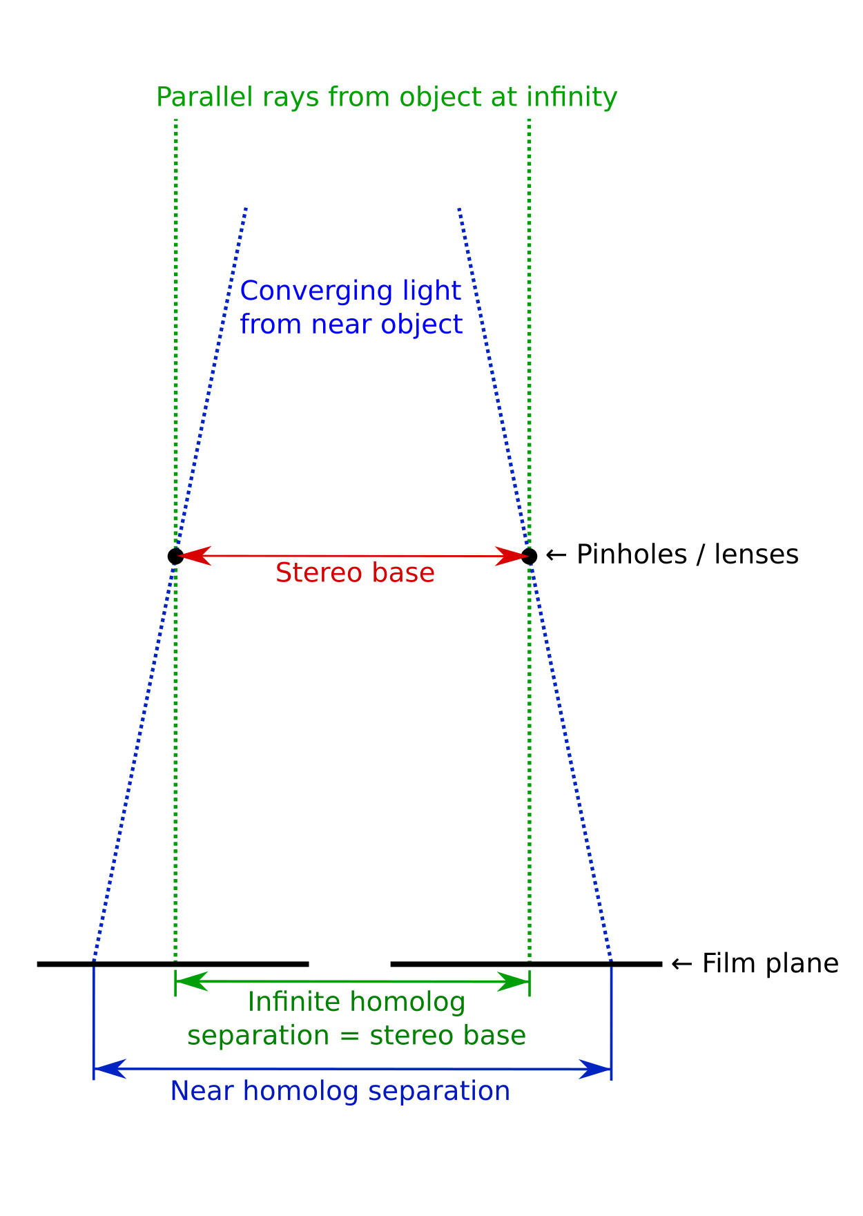
Film Gates: the cause of the in-camera stereo window
If the stereo camera has standard film gates that are centered on the optical axis, the edges of the film gates will also be separated by 65 mm. In other words, they occur at the same separation as the far homologs. This is why, when the far homologs are “mounted to infinity” (i.e. spaced at the interocular spacing of the viewer lenses), a camera with centered film gates will have the window set at infinity as well. By pushing the film gates further apart from the centre of the camera, the stereo window will be pushed closer in 3D space when the film chips are swapped in order to view them in a viewer.
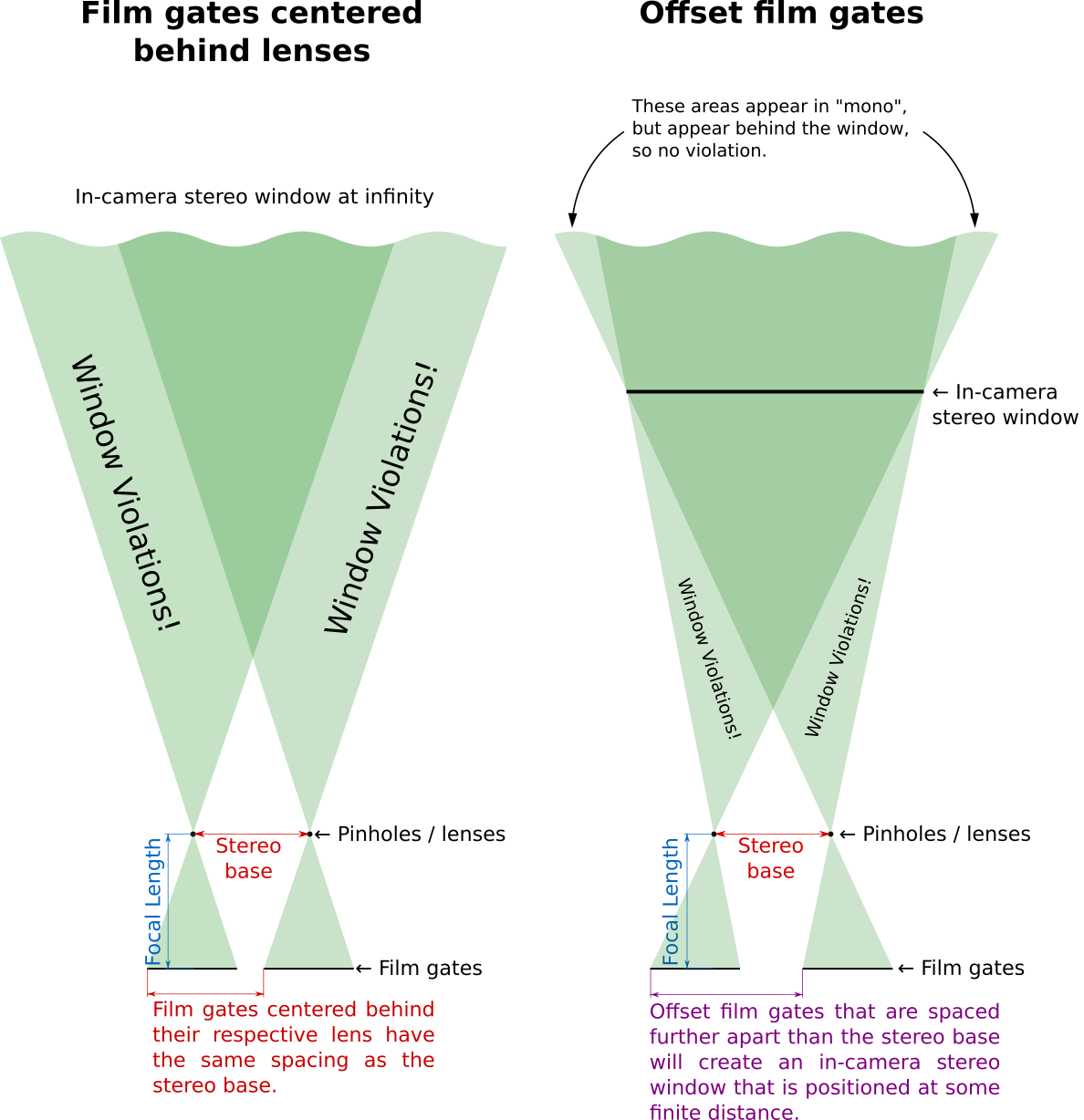
There’s a lot going on in the above figure, so let me break it down. This is a top-down view of a stereo camera pointing at a scene. The translucent green hourglass shapes represent the field of view (the projection of the frustum) captured by the lenses and projected onto the film plane. The pale green areas in the scene are only captured by one lens, while the objects in the dark green area are recorded onto both film chips.
Just What Is a Window Violation?
There are a few areas of the scene which are only captured by a single camera. First, consider the “mono” regions behind the stereo window at the top of the right hand image above. Tracing the edge of the frustum back towards the camera, it’s clear that these regions will be recorded onto the outside edges of the two frames. Although these regions are not in stereo, they are typically not bothersome as the objects are here are behind the stereo window and appear simply to be occluded by the window. It is a common occurrence in everyday life that an object blocks the view of something from one eye but not the other, and our brains can handle this situation quite well. Even so, if these take up a unreasonably large proportion of the total view, you may experience some “retinal rivalry” — a ghosting of flickering sensation where the signals from each eye are in competition with each other since one eye is receiving no information about objects in this region. This can occur when too much depth is recorded and you try to save the shot by adjusting the stereo window by excessively cropping the image.
Much more troublesome are the areas labelled “window violations” in the above figure. Objects in these areas are physically in front of the location of the stereo window, but they are only captured with one of the lenses. Given the incredibly wide field of view of human vision (compared to conventional photography) this is a situation which our brains have very little experience interpreting. To appreciate why this window violations are such an off-putting experience, we must progress from thinking only about infinitely small homologous points to macroscale objects. Typically, adjacent homologs belong to the same “object” (for example, a tree branch, a board in a fence, or an arm of a person are each composed of countless infinitesimally small homologs). It may be the case that portions of the object (i.e. some of its constituent homologs) may be captured onto both film chips, but the remaining portion of the object is only visible by the FOV of one lens. This is the situation where a window violation becomes extremely objectionable. Since the brain has been provided with depth information for the central portion of the object, it can correctly situate the object at a distance closed than the window. However, the edge of the object is only visible to one eye, which is a situation that only occurs when an object is occluded from one eye.† So there are conflicting depth cues: first, that the object is in front of the window, and second, that the edge of the object is occluded by the window, and therefore must be behind the window. You may have trouble judging the location of the object, or you may experience retinal rivalry or general unease. In general, viewers will want to avoid looking at this area of the image as it is unpleasant to view, thereby depriving your audience of the greatest pleasure of wide FOV 3D photography — scanning one’s eyes over the image, examining each corner and edge for all the small details.
What does this all mean — are there any practical implications to any of this? Well, as I hope you can see in the last graphic, it’s really the stereo base and the film gate size and separation which determine the maximum usable frame width for the final stereo image. To get a better intuition for the mathematical relationship between these factors, please check out the calculator and visualization tool I developed in conjunction with this article.
If you are use a dedicated stereo camera, you needn’t be too concerned about the in-camera stereo window, and really it just gives an indication of how much wiggle room you have when mounting. Likewise, if you are using a pair of (mono) cameras, it shouldn’t be too much of a problem to crop a small amount off the inner edges of the frame when mounting. I think the main concern would be if you are designing a camera that exposes onto a single roll of film. Here you must consider the whether the film advance (Wpair) and the stereo base (B) will allow you to attain the final image size (Wchip) that you desire. In order to be sure that you are collecting enough overlapped image area, you need to know what size of frame you want to get in your final stereo image.
Footnote
* Where did this 53 mm come from? Why 3 mm larger than the final format? Well, at the risk of opening another can of worms, 3 mm is a reasonable value for the maximum acceptable on-film deviation, MAOFD. Why? Well there are many different ways of calculating this, and different people disagree, some say 2.5mm, others 2.7 or 2.8 and others say 3 mm. I think one reasonable way to calculate MAOFD is to consider the difference between the viewer lens spacing and the spacing of the apertures of the mount. Typically, viewers have a lens spacing of 65 mm. Recall that we don’t want homologs separated by a distance larger than this amount because it causes the eyes to diverge. Then consider the mount — my mounts have the apertures separated by 62 mm. Recall that we don’t want any homologs to be separated by a distance narrower than the mount aperture if the object crosses the edge of the frame since this will cause a window violation. So the MAOFD equals 65 mm – 62 mm = 3 mm. You might ask: Why not make mounts with some other spacing? That is a fair question, and this is why there is some dispute as to what constitutes the actual maximum acceptable on-film deviation. There are other more fundamental limits — how much depth of field do you have, can you sharply capture objects that are really close? How much can you converge your eyes and fuse an image? How good is the off-axis performance of your viewer lenses? It largely comes down to personal preference, different people have a different tolerance for each of these factors.
† Typically when an object blocks the sight-line of only one eye, the eye on the same side as the blocking object will be blocked from receiving the information. To illustrate this, close your right eye and focus on an object a few meters away. Hold your hand about 30 cm from your head and slowly move your hand into your field of view, from left to right, stopping as soon as your left eye is totally blocked from seeing the object. Now open your right eye. You should be able to see the object (or at least part of it) around the right edge of your hand. So an object will block the sight-line of the eye that is on the same side as the object. However, in the case of a window violation it is the opposite situation. If there is a window violation on the left side of the frame, it is the right eye which receives no information, while the left eye which is presented with a bit more expansive view of the offending object. This atypical “crossed wires” situation is a major cause of the unease resulting from window violations.